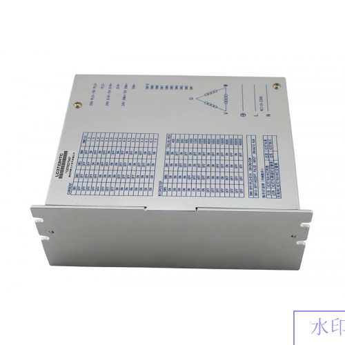
LC3722HTC 3ph NEMA34 NEMA42 NEMA52 Stepper Motor Driver 110-220VAC 7A
- Model: LC3722HTC
- Shipping Weight: 1Kg
- In Stock:20
- Manufactured by: LiChuan


 0 reviews
3ph NEMA34 NEMA42 NEMA52 Stepper Motor Driver 110-220VAC 7A
LC3722HTC Three-phase hybrid stepping motor drive
LC3722HTC is a kind of three-phase hybrid stepping motor drive based on DSP control , it is a new generation of digital stepper motor drive made up of the advanced DSP control chip and three-phase inverter driver module combine together.The drive voltage is AC110V - 220 v, adaptive current is below 7.0 A,57-130 mm external diameter of the various types of three-phase hybrid stepping motor. The inner of drive adopts a circuit similar with servo control principle.the circuit can make the motor run smoothly, little vibration and noise.When motor is in high speed, the torque is much higher than the two and five phase hybrid stepping motors.Step positioning accuracy up to 60000 / rolls. The products are widely used in engraving machine, medium-sized nc machine, computer embroidery machine, packaging machinery and other high resolution of large and medium-sized CNC equipment.
Features:
·High performance and low price
·Equipped with 16 files of uniform angle constant torque subdivided ,the max resolution is 60000 steps/roll
·The highest response frequency up to 200 KPPS
·when step pulse stops for more than 1.5 S, coil current will be reduced
to half of the rated current automatically
·Photoelectric isolation, signal input/output
·Drive current 1.3A/phase to 7.0 A/phase ,16 files is adjustable
·Single power input, the voltage range: AC110V - 220 v
·Phase memory function (note: when stop inputting for more than 3 seconds, drive will bear motor phase in mind automatically at the time, back to electricity or WF signals from low level to high , drive will recovery motor phase automatically)
current setting
Drive working current is set by the D1 - D4 terminals, running current set switch for normal work output current (see table below)
|
running current |
DV3722 |
1.3 |
1.6 |
2.1 |
2.3 |
2.5 |
3.0 |
3.2 |
3.5 |
|
D1 |
OFF |
OFF |
OFF |
OFF |
OFF |
OFF |
OFF |
OFF |
|
|
D2 |
OFF |
OFF |
OFF |
OFF |
ON |
ON |
ON |
ON |
|
|
D3 |
OFF |
OFF |
ON |
ON |
OFF |
OFF |
ON |
ON |
|
|
D4 |
OFF |
ON |
OFF |
ON |
OFF |
ON |
OFF |
ON |
|
|
running current |
DV3722 |
4.0 |
4.5 |
5.0 |
5.3 |
5.8 |
6.2 |
6.6 |
7.0 |
|
D1 |
ON |
ON |
ON |
ON |
ON |
ON |
ON |
ON |
|
|
D2 |
OFF |
OFF |
OFF |
OFF |
ON |
ON |
ON |
ON |
|
|
D3 |
OFF |
OFF |
ON |
ON |
OFF |
OFF |
ON |
ON |
|
|
D4 |
OFF |
ON |
OFF |
ON |
OFF |
ON |
OFF |
ON |
|
Segment setting
Drive subdivided is set by D5 - D8 terminals , 16 files in total, D9 and D10 are for functionality setting. Schedule such as: division number(pulse/roll)
|
Division number |
400 |
500 |
600 |
800 |
1000 |
1200 |
2000 |
3000 |
|
D5 |
ON |
ON |
ON |
ON |
ON |
ON |
ON |
ON |
|
D6 |
ON |
ON |
ON |
ON |
OFF |
OFF |
OFF |
OFF |
|
D7 |
ON |
ON |
OFF |
OFF |
ON |
ON |
OFF |
OFF |
|
D8 |
ON |
OFF |
ON |
OFF |
ON |
OFF |
ON |
OFF |
|
Division number |
4000 |
5000 |
6000 |
10000 |
12000 |
20000 |
30000 |
60000 |
|
D5 |
OFF |
OFF |
OFF |
OFF |
OFF |
OFF |
OFF |
OFF |
|
D6 |
ON |
ON |
ON |
ON |
OFF |
OFF |
OFF |
OFF |
|
D7 |
ON |
ON |
OFF |
OFF |
ON |
ON |
OFF |
OFF |
|
D8 |
ON |
OFF |
ON |
OFF |
ON |
OFF |
ON |
OFF |
|
D9 |
ON,Double pulse: PU is forward direction step pulse signal, DR is reverse direction step pulse signal |
|||||||
|
OFF,Single pulse: PU is step pulse signal, DR is direction control signals |
||||||||
|
D10 |
Automatic detection switch (when OFF receiving external pulse, when ON runs at a speed of 30 r/min in internal drive) |
|||||||
Note: Custom division number according to customers’ request.
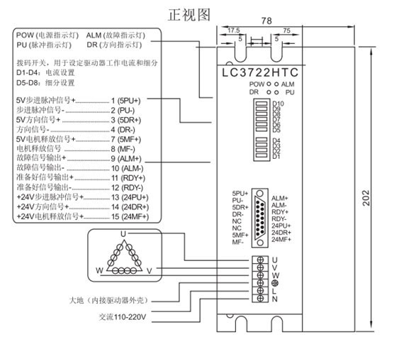
Drive wiring/size sketch map

Note:
1, The input voltage cannot exceed ac 220V;
2, The input control signal level is 5v,current limiting resistor is required when higher than 5 v
3, Falling edge is effective when inputting pulse signal ;
4, Drive will stop working when temperature over 80 degrees , failure indicator light ALM on , until the drive temperature drops to 50 degrees, the driver needs to be on the electricity can be restored. Overheating protection with radiator, please.
5,Over current (load short out) fault indicator light ALM on, please check the motor wiring and other short out fault, it needs to electrified again to recover after ruling out.
6, No motor fault indicator ALM on, please check the motor connection, it needs to electrified again to recover after ruling out.
Pin function statement
|
Port definitions |
Connector pins no. |
mark symbol |
Function |
Annotation |
|
DB 15 |
1 |
5PU+ |
input signal photoelectric isolation plus port |
connect + 5 v power supply, + 5 v to + 24 v can all be driven, higher than + 5 v, current limiting resistor is required |
|
2 |
PU- |
DP9=OFF,PU is stepping pulse signal |
Falling edge effective, when the pulse change from high to low,the motor takes a step. input resistance 220ohm, requirement: low level 0-0.5 V, high level 4-5 V, pulse width > 2.5 mu s |
|
|
DP9=ON,PU Is plus direction stepping pulse signal |
||||
|
3 |
5DR+ |
input signal photoelectric isolation plus port |
connect + 5 v power supply, + 5 v to + 24 v can all be driven, higher than + 5 v, current limiting resistor is required |
|
|
4 |
DR- |
DP9=OFF,DR is direction control signal |
Used to change the motor turning.input resistance 220ohm, requirements: low level 0-0.5 V, high level 4-5 V, pulse width > 2.5 mu s |
|
|
DP9=ON,DR is reverse direction stepping pulse signal |
||||
|
7 |
5MF+ |
input signal photoelectric isolation plus port |
connect + 5 v power supply, + 5 v to + 24 v can all be driven, higher than + 5 v, current limiting resistor is required |
|
|
8 |
MF- |
motor release signal |
Shut off the motor terminal current when effective (low level) , drive stop working, the motor in the free state. |
|
|
9 |
ALM+ |
Drive failure output signal photoelectric isolation plus port |
when over-current, overheating fault appear, drive output the trouble signal, it is effective (high level) |
|
|
10 |
ALM- |
Drive failure output signal photoelectric isolation minus port |
|
|
|
11 |
RDY+ |
drive ready to output signal of photoelectric isolation plus port |
Driver’s status is normal, when ready to accept the signal of Controller,it is effective (low level) |
|
|
12 |
RDY- |
drive ready to output signal of photoelectric isolation minus port |
|
|
|
13 |
24PU+ |
input signal photoelectric isolation plus port |
· +24V drivable
|
|
|
14 |
24DR+ |
input signal photoelectric isolation plus port |
+24V drivable |
|
|
15 |
24MF+ |
input signal photoelectric isolation plus port |
+24V drivable |
|
|
|
12 |
LN |
power supply |
power supply:AC110-220V |
|
3 |
PE |
base line |
Ground(Inscribe shell of drive) |
|
|
4 |
U |
|
|
|
|
5 |
V |
motor wiring |
||
|
6 |
W |
|
There are currently no product reviews.


![8}E]2NPB`GV}F93$D$_UTCY](http://g03.a.alicdn.com/kf/HTB1fet6IXXXXXbZaXXXq6xXFXXX7/220249214/HTB1fet6IXXXXXbZaXXXq6xXFXXX7.jpg?size=3145&height=79&width=112&hash=c9b097e0c32e194fd63d68f58c9d106e)
