36W-200W 24V-50VDC All Digital Brushed DC Servo Motor Driver JMC MCDC706
- Model: MCDC706
- Shipping Weight: 0.5Kg
- In Stock:50
- Manufactured by: JMC


 0 reviews
36W-200W 24V-50VDC All Digital Brushed DC Servo Motor Driver JMC MCDC706
Working voltage:24-50VDC
Optical coupling isolation servo reset input interface ERC
Have real-time virtual oscilloscope, can display the parameter curve about the motor running current, speed ,tracking error and so on.
Can set the PID parameters of position loop, speed loop and current loop.
You can choose the encoder according the encoder cable. and you can setting pulse equivalent according the inside electronic gear ratio.
Using RS232C port, through PC testing software change parameter.
Over-current, I2T, overvoltage , undervoltage, overheating, speeding and differential protection
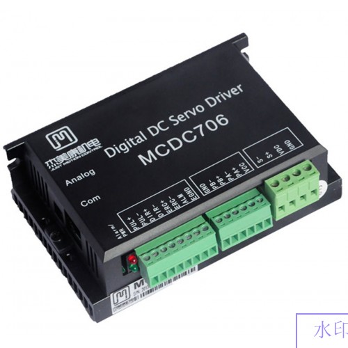
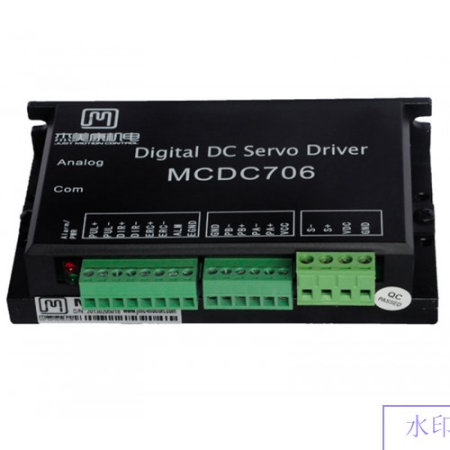
When the indicator light turns green, it means running. when the indicator light turns red, it means protection or offline.
Typical applications:
Suitable for inkjet printing and dispensing machine.
Performance indicators:
MCDC706 is all-digital DC servo drive system adopts high-performance digital signal processor (DSP) and integrated circuit, and come out to be a cost effective product with simple circuit, high integration, easy operation, and strong practicability. MCDC706 provide three feedback loops:(position loop, velocity loop and current loop). Three work control mode: position, velocity and torque. MCDC706 matches with DC servo motor under 24~50V and 30~300W.
Electrical indicators:
|
Instructions |
Min |
Typical values |
Max |
|
Supply voltage (VDC) |
24V |
36V |
50V |
|
Output current (A) |
- |
6 |
- |
|
Input current (mA) |
- |
10 |
- |
|
Work pulse frequency (KHZ) |
- |
- |
250 |
|
Low level pulse time (US) |
2.5 |
- |
- |
Environmental indicators:
|
cooling |
natural cooling or forced convection |
|
|
Environment |
Space |
Avoid dust,oil frost and corrosive gases |
|
Work temperature |
0~+50℃ |
|
|
Storage temperature |
-20℃~+80℃ |
|
|
Humidity |
40~90%RH |
|
|
Dimension |
- |
118×76×35 |
|
Weight |
- |
300g |
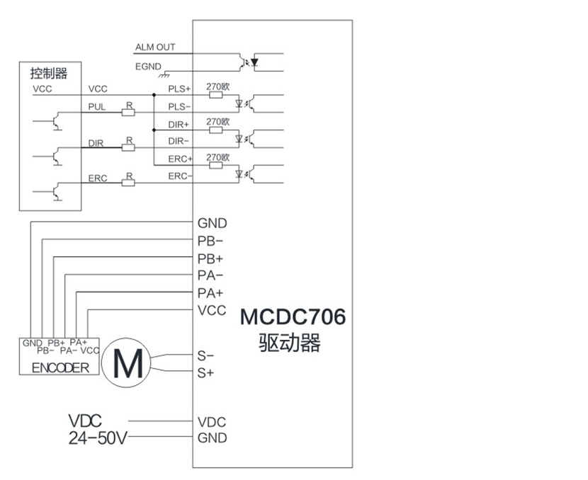
P1 input signal interface description:
|
symbol |
function |
Description |
|
PUL+ |
Input signal photoelectric isolation positive end |
Connected to the +5V power supply, +5V~+24V can be driven, higher than +5V need to limit the current resistance |
|
PUL- |
Step pulse signal |
Down along the effective, whenever the pulse from high to low when the motor to take one step, the input resistance 220ohm, the requirements: low level 0-0.5, high level 4-5V, pulse width of less than 2.5US |
|
DIR+ |
Input signal photoelectric isolation positive end |
Connected to the +5V power supply, +5V~+24V can be driven, higher than +5V need to limit the current resistance |
|
DIR- |
Direction control signal |
For changing the motor steering, input resistance 220ohm, requirements: low level 0-0.5, high level 4-5V, pulse width less than 2.5US |
|
ERC+ |
Input signal photoelectric isolation positive end |
Connected to the +5V power supply, +5V~+24V can be driven, higher than +5V need to limit the current resistance |
|
ERC- |
Motor release signal |
Active (low level) to cut off the motor coil current, the driver stops working, the motor is in a free state |
|
ALLM+ |
Alarm output positive |
|
|
EGND |
Alarm output negative pole |
P2 motor encoder interface description
|
Terminal number |
symbol |
symbol |
Name |
description |
|
1 |
Motor line |
S- |
DC brushed motor - end |
|
|
2 |
S+ |
DC brushed motor +end |
||
|
3 |
VDC |
Input DC power supply+ |
DC24V-50V |
|
|
4 |
Power input |
GND |
Input ground |
0V |

There are currently no product reviews.


