Your cart is empty.


2 phase Closed loop Step servo driver for NEMA23 motor 24V-48VDC 6A JMC 2HSS57
- Model: 2HSS57
- Shipping Weight: 0.5Kg
- In Stock:100
- Manufactured by: JMC
 0 reviews
2 phase Closed loop Step servo driver for NEMA23 motor 24V-48VDC 6A JMC 2HSS57
- Full closed loop control
- Motor with standard 1000 line encoder
- It save energy and achieve nearly 100% output torque .
- Micro step setting range is 2-256
- High speed response , High speed
- Optical isolation fault alarm output interface ALM
- Current loop bandwidth: (-3dB) 2KHz (typical value)
- Speed loop bandwidth: 500Hz (typical value)
- Position loop bandwidth: 200Hz (typical value)
- RS232 serial communication available to download or change the parameters
- Optical isolation fault alarm output interface ALM
- Over current, I2T, over voltage, under voltage,temperature, speeding, over-differential protection
- Alarm clear input ENA
Typical applications:
CNC machine ,cutting machine ,engraving machine
Introduction
2HSS57 two-phase hybrid stepper servo drive system integrated servo control technology into the digital step driver. It adopts typical tricyclic control method
which include current loop,speed loop and position loop.This product has the advantage of both step and servo system, and it’s a highly cost-effective motion control products.
Electrical Specifications
|
Parameters |
Min |
Typical |
Max |
Unit |
|
Supply voltage |
24V |
36V |
60V |
VDC |
|
Output Current (Peak) |
- |
- |
6.0 |
Amps |
|
Logic Input Current |
- |
10 |
- |
mA |
|
Pulse input frequency |
- |
- |
200 |
KHz |
|
Low Level Time |
2.5 |
- |
- |
µsec |
Environment
|
Cooling |
Natural Cooling or Forced Convection |
|
|
Environment |
Storage Space |
Avoid dust, oil frost and corrosive gases |
|
Ambient Temperature |
-20°C - +80°C |
|
|
Humidity |
<80%RH |
|
|
Vibration |
5.9m/s² Max |
|
|
Storage Temp. |
-20°C - +80°C |
|
|
Weight |
Approx. 300 gram |
|
Microstep Resolution Setting
|
Step / Rev. |
SW3 |
SW4 |
SW5 |
SW6 |
|
Default |
ON |
ON |
ON |
ON |
|
800 |
OFF |
ON |
ON |
ON |
|
1600 |
ON |
OFF |
ON |
ON |
|
3200 |
OFF |
OFF |
ON |
ON |
|
6400 |
ON |
ON |
OFF |
ON |
|
12800 |
OFF |
ON |
OFF |
ON |
|
25600 |
ON |
OFF |
OFF |
ON |
|
51200 |
OFF |
OFF |
OFF |
ON |
|
1000 |
ON |
ON |
ON |
OFF |
|
2000 |
OFF |
ON |
ON |
OFF |
|
4000 |
ON |
OFF |
ON |
OFF |
|
5000 |
OFF |
OFF |
ON |
OFF |
|
8000 |
ON |
ON |
OFF |
OFF |
|
10000 |
OFF |
ON |
OFF |
OFF |
|
20000 |
ON |
OFF |
OFF |
OFF |
|
40000 |
OFF |
OFF |
OFF |
OFF |
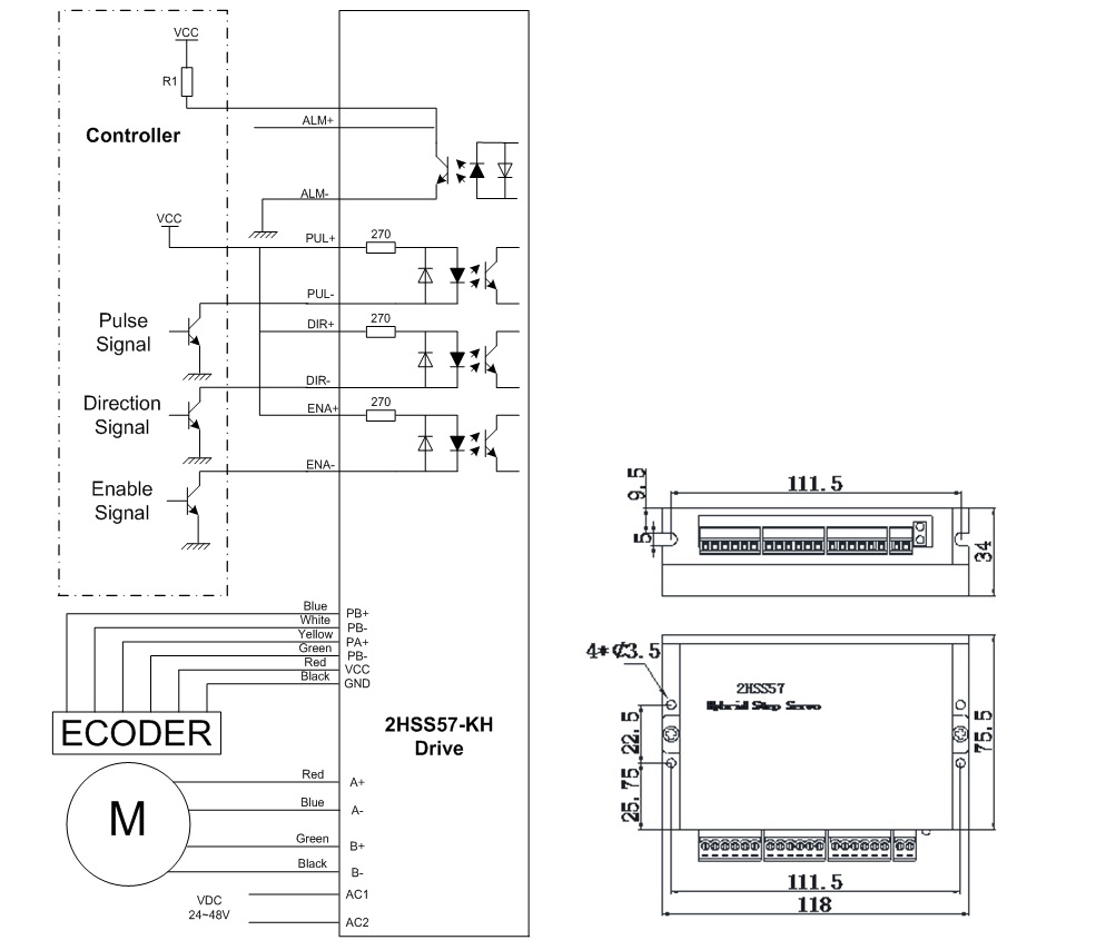
ALM signal output ports
|
Port |
Symbol |
Name |
Remark |
|
1 |
ALM+ |
Alarm output + |
|
|
2 |
ALM- |
Alarm output - |
Control signal input port
|
Port |
Symbol |
Name |
Remark |
|
1 |
PLS+ |
Pulse signal + |
High level 4~5V |
|
2 |
PLS- |
Pulse signal - |
Low level 0~0.5V |
|
3 |
DIR+ |
Direction signal+ |
High level 4~5V |
|
4 |
DIR- |
Direction signal- |
Low level 0~0.5V |
|
5 |
ENA+ |
Enable signal + |
High level 4~5V |
|
6 |
ENA- |
Enable signal - |
Low level 0~0.5V |
Power Interface Ports
|
Port |
Identification |
Symbol |
Name |
Remark |
|
1 |
Motor Phase Wire Input Ports |
A+ |
Phase A+(Red) |
Motor Phase A |
|
2 |
A- |
Phase A- (Blue) |
||
|
3 |
B+ |
Phase B+(Green) |
Motor Phase B |
|
|
4 |
B- |
Phase B-(Black) |
||
|
5 |
Power Input Ports |
VCC |
Input Power + |
24-50VDC |
|
6 |
GND |
Input Power- |
There are currently no product reviews.
